Blinds control V?


#1

I have had my blinds up and running for quite a while now with the V2 firmware and i have always wanted to add a button, i see that this can be done now but you have to be on a newer firmware, as stated i am on V2 which is not compatible to add a button ? i have search everywhere on the forum for a working download link for the newer firmware to no avail.

The only one i have found working is the v6 firmware but i would like the latest build if possible, does anyone have a working download link that they can post up.


#2

The new download link as follows
https://mountaineagle-technologies.com.au/tasmota/mk-blindcontrol.bin
you will need to do a manual upgrade as the Auto method via the GUI is not working in previous version
the new version has resolved this problem


#3

Thank you Mountain and will do…


#4

Thats great. If you need the modification for the PCB I can re post it for you …it should be in one of the old posts on this site. 10k resistor to be soldered and a couple of wires for the switch


#5

“If you need the modification for the PCB I can re post it for you”

That would also be great…and just to clarify i need to use the pins inside the enclosure to flash the device / board manually …Thank you


#6

Using the pins inside is last resort. You should be able to manually to a upgrade via OTA via the GUI.
If you are running V6 and above this would be in firmware manual option then you select the file from your pc.

If you are running V2 I think you enter the ipaddress/firmware from browser.
eg. 192.168.0.220/firmware
ipaddess being the address of the device.

try ipaddress in a browser without firmware and it should show some basic info and the address you need to put in url for firmware upgrade.
username default is admin and default password is password, unless you changed it in setup.

The switch is connected (N/O) push button between PGM and centre pin as shown
A 10k resistor is connected between centre pin and RUN pin. I soldered on the under side of PCB

Also in setup you need to enable remote switch


#7

Thank you once again, this will be my weekend project when the resister arrives and hopefully it will go well without any issues…

Just a little update i have now loaded the new firmware on and wondered why i did not do this earlier, as it clear and the ease of use is great, i did have a bit of a issue with the firmware timing out using a Usb to Ttl Adapter, but i worked it out that i needed more power for it to stay connected.

after reading a bit more about the new firmware on the forum i came across this issue regrading voltage which i wish i had read that before, as it was the exact same issue i had but all sorted now.

" (Note on .FTDI Adaptor, and voltage output.)
I had the problem of header failure when writing to eprom etc and time out errors, the FTDI was only giving 3.7 volts instead of 5V. not enough juice .
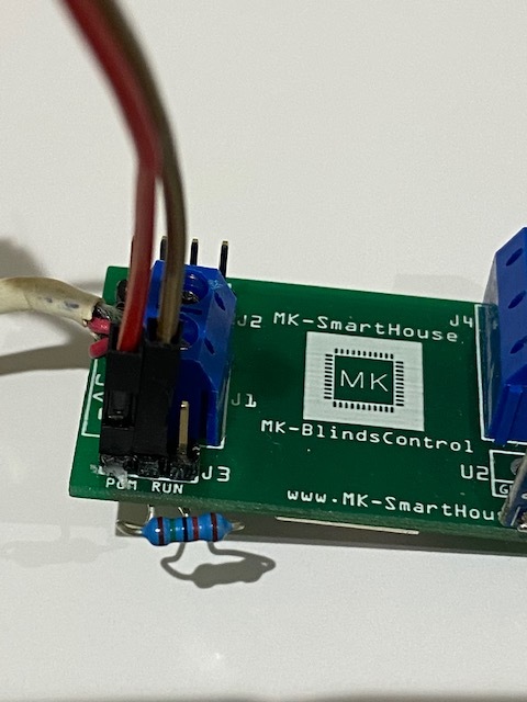
I connected the 5v from power supply to pcb as normal to overcome the shortfall ONLY on the 5V input of the PCB…Not to the esp8266 directly… "

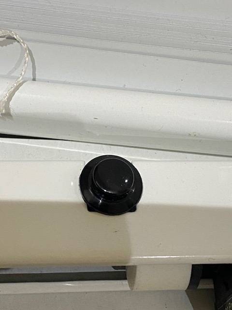
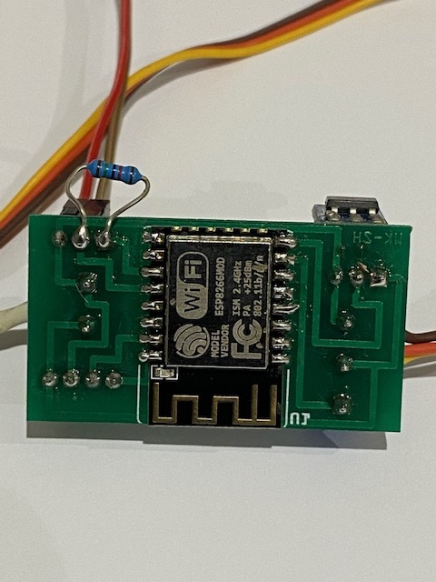
Anyway i’m just waiting for my resistor to arrive then to fit the button then its done.

Update…
Parts came this weekend and soldered the resister onto the board as stated, attached my push button, selected yes in the setup firmware for button, restarted device and voila all is working great, and thanks once again for this firmware.


#8

Thanks for up date.
And yes I had same problem when flashing via adaptor so I kept the 5v connecteted to the pcb while flashing with FTDI adaptor.